
I’m working on N.C Sketcher for my final robotics class at RIT. See other posts about this system on the project hub.
While I have been sinking some time into exploring computer vision processes, I have also been working hard on coming up with an actual hardware platform. While benchmarking existing drawing machines, I made a few decisions about the geometry of my design based on ease of use, cost, and the necessary workspace. Now I need to take those decisions, select components, and design an assembly that implements my design goals. Just to review, These goals include:
- The machine takes up a minimal amount of space. That means that the robot’s workspace shouldn’t change based on its position (like axiDraw and similar designs).
- The machine can simulate different drawing patterns (line drawing, sketching, calligraphy). Obviously, this goal is tied to the software controlling the machine, but I want to make sure the hardware is at least capable of performing these actions
- The machine is able to draw with sub-mm precision, and can move quickly. This isn’t a hard requirement, however.
There are a few other minor goals, but these are the most important. So, let’s start!
Drawing with style

Sketching is obviously not an exact science, but there are several commonly-used methods to produce different parts of an image. for pencil drawings, the stylus is usually held almost upright for edges and details (to get the sharp pencil point), and shallower angles for shading and filling regions (though some styles may use Hatching and Cross-hatching with the pencil still upright.
I need 5 degrees of freedom (or DoF) to accomplish all of these movements. two of these axes are Cartesian, moving the pen tip around in the x and y directions. The last three axes follow the Spherical coordinates Φ,θ, and r, which control the orientation and position of the pen tip. The visualization below should help explain.

I will need to come up with a pen holder that can manipulate a pen in these three ways, and an X-Y grantry that can move this pen holder around.
Fast n’ Strong
Since I am aiming for a cantilevered design, I want to make sure that the floating axis is not too flexible. This would be a major issue, if the pressure applied by the machine changes dramatically depending on how far out on the axis it is operating. I want to select an axis that is rigid enough, but I also want to make sure that I choose a rail that is light enough so to not hamper the movement of the fixed axis.

I went with a pair of round rails for the floating axis, as these are most commonly used in 3D printers and other CNC equipment (making them easy to get and low cost), however they are available in several materials and sizes. To test this, I calculated the deflection rates of several different types of rods. I made a (probably not accurate) assumption that the deflection of 2 of the rods would be equal to half of a single rod.
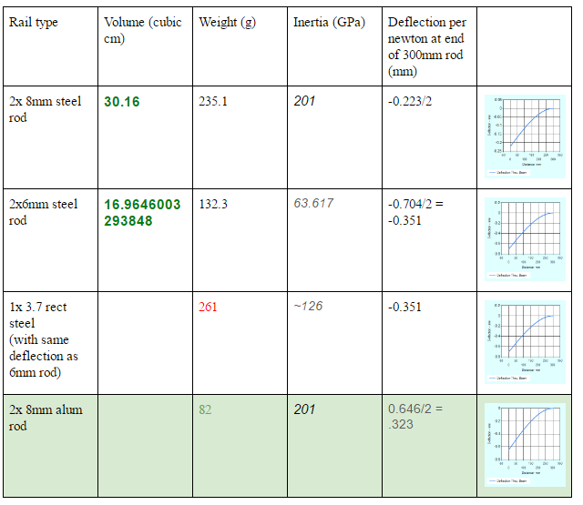
From the calculations, 8mm rod appeared to be the ideal choice. I wanted to go with Anodized aluminum rod, as it has slightly greater deflection but weighs a lot less. However, even anodized aluminum is softer than the hardened steel balls within a standard LM8UU linear bearing, which would eventually cut channels into the rods and reduce their precision. Using aluminum would require the use of self-lubricating plastic bearings, such as the Drylin line of bearings by Igus. The extra cost and longer lead times associated with these parts were bigger issues than the extra weight steel rods would bring with it, so we are going with steel for the X axis. The Y axis is based on a piece of OpenBuild’s Aluminum extrusion, which when combined with their V wheels produces a very rigid platform.
I also want to ensure that I select motors and a drive system that allows the machine to accelerate at a reasonable rate, and has a decent top speed. the NEMA 17 “Pancake” motor seemed like a good choice, as it is only 20mm in height, which fits the openBuilds rail perfectly, and weighs half that of a standard stepper motor. To select a pulley diameter which produces the best possible performance, I created a simulation in Excel (should have used Matlab, yes…) that calculated the time to travel a certain distance, based on the reported max. torque of the motor (I assumed 50% of that value as a safety margin).


Ok, so those numbers happen to average out to the value I went with, maybe I’m biased. Either way, 10mm gave a good travel time for a large range of travel distances. I find it interesting, however, that most 3D printers use a much smaller radius (or the order of 3-5mm typically).
These calculations went on and on for the remaining axes, but I’m sure this is starting to get a bit tiresome to read through. Let’s fast forward a bit…

woah, too far! go back!

Ok, sorry for spoiling the ending. Here is what I came up with after a few weeks of modeling. I could go on for hours about how I decided to make each of the components, but I’ll leave that as an exercise to the reader ;). I’ll share some common rules I followed:
- Make the important parts modular. it’s a lot simpler to reprint smaller parts, so make the things that have to interface together separable from the main component.
- add extra tolerance to surface mates where the parts will be connected on their vertically printed surfaces (as opposed to the top and bottom, as it comes off the 3D printer)
- threaded holes are cool, but if they are blind (no opening at the other end), leave lots of extra space.
- A E S T H E T I C s matter, make it look streamlined. But don’t let the visual appearance get in the way of the mechanics.
- I had a nice acrylic cover planned over the Y axis, but that would limit accessibility and constrain the wire harness to a very small space. I’ve since removed that part and will “leave it for Rev. B”.
As you have seen, I’ve already built these parts and am currently working on wiring the machine up. I hope to get it moving by the end of this week, so hopefully I will have another post soon!
